An impeller is a rotating component designed to transfer energy from the motor to the fluid, increasing its velocity and pressure as it moves through the machine. A good impeller design ensures optimal fluid dynamics, minimizes energy losses, and contributes to the longevity of the turbomachinery equipment.
In this article, we will discuss the details of impeller design, its challenges, and their solutions. We will also examine how engineering simulation, especially cloud-native simulation, enables engineers to create more efficient and reliable impellers.
Basic Principles of Impeller Design
Impeller design uses fundamental fluid dynamics and energy transfer principles to function effectively. The primary function of an impeller is to convert mechanical energy from a motor into kinetic energy in the fluid. This process is governed by several fundamental principles and equations.
Bernoulli’s Equation
One of the foundational equations in fluid dynamics is Bernoulli’s equation, which describes energy conservation in a flowing fluid. It states that the total mechanical energy of the fluid remains constant along a streamline. The equation is given by:
$$ P = \frac{1}{2}\rho v^2 + \rho gh = constant $$
where
- \(P\) is the static pressure.
- \(\rho\) is the fluid density.
- \(v\) is the fluid velocity.
- \(g\) is the acceleration due to gravity.
- \(h\) is the height above a reference point.
Euler’s Turbomachinery Equation
Another critical principle is Euler’s turbomachinery equation, which relates the change in fluid energy to the impeller’s geometry and rotational speed. It is given by:
$$ \Delta H = \frac{U_2 V_{u2} – U_1 V_{u1}}{g} $$
where
- \(\Delta H\) is the head increase imparted to the fluid.
- \(U\) is the tangential velocity of the impeller.
- \(V_u\) is the tangential component of the absolute velocity of the fluid at the inlet (1) and outlet (2) of the impeller.
- \(g\) is the acceleration due to gravity.
This equation is essential for determining the work done by the impeller on the fluid and is used to calculate the pressure increase provided by the impeller.
Key Design Parameters
The design of the impeller itself involves several key geometric parameters that influence its performance. These include:
- Impeller Diameter: The impeller diameter impacts both the head and flow rate. Larger diameters increase head and flow but also raise energy consumption. The relationship is approximated by the affinity law: \(H \propto D^2\)
- Blade Angle: Blade angles at the inlet (\(\beta_1)\) and outlet (\(\beta_2)\) are crucial for smooth fluid entry and exit, minimizing flow separation and turbulence. Optimized angles enhance energy transfer efficiency.
- Number of Blades: More blades reduce fluid slip and improve efficiency but increase manufacturing complexity. The optimal number balances efficiency and practical considerations.
- Blade Shape and Curvature: Curved blades guide fluid better than straight ones, reducing turbulence and energy losses. The blade shape is tailored to specific applications, such as radial, mixed-flow, or axial-flow impellers.
- Impeller Width: Impeller width affects flow rate and efficiency. Wider impellers handle larger flow rates but may increase friction losses. Narrower impellers are more efficient but support lower flow rates.
- Material Selection: Material choice impacts durability and resistance to wear and corrosion. Common materials include stainless steel, cast iron, and various alloys, selected based on operating conditions.
- Surface Finish: A smooth surface finish on blades and shrouds reduces friction and turbulence, enhancing hydraulic efficiency. Precision casting and surface coatings can improve the surface finish.
Types of Impellers
Table 1 below shows the types of impellers used in turbomachinery equipment (pumps or turbines).
| Impeller Type | Definition | Best for |
|---|---|---|
| Open Impeller | Open impellers have vanes attached to a central hub without any shrouds. This design allows for easy passage of solids and simplifies cleaning and maintenance. They are ideal for pumping slurries, sewage, and other fluids containing large particles. | Handling solids, liquids with high viscosity, and applications requiring frequent cleaning |
| Semi-Open Impeller | Semi-open impellers feature a central hub with vanes partially covered by a shroud on one side. This design balances the durability of closed impellers and the ease of cleaning of open impellers. They can handle moderately viscous fluids and small solids, making them suitable for wastewater treatment and industrial processes. | Liquids containing small amounts of solids, moderate viscosity fluids |
| Closed Impeller | Closed impellers are fully enclosed by shrouds on both sides of the vanes, creating a sealed chamber. This design enhances efficiency by reducing fluid recirculation and maintaining a stable flow. | Clean liquids, high-efficiency applications, and high-pressure systems |
| Vortex Impeller | Vortex impellers have a recessed design where the vanes do not directly contact the pumped fluid. Instead, they create a vortex that moves the fluid, allowing large solids and fibrous materials to pass through without clogging. | Handling large solids, fibrous materials, and wastewater with heavy debris |
| Recessed Impeller | Recessed impellers, or “torque flow” impellers, generate centrifugal force uniquely. Instead of directly accelerating the liquid down the vanes, these impellers use their vanes to create a hydraulic coupling. This coupling spins the slurry within the pump casing, producing the necessary discharge pressure. Because the vanes are mostly out of the normal flow path, erosion is minimized, and the vanes can be thinner compared to other impeller styles. | Delicate solids, shear-sensitive liquids, and minimizing wear |
| Cutter Impeller | Cutter impellers are equipped with cutting blades integrated into the vanes. These blades chop up fibrous materials and solids as the fluid moves through the pump, preventing clogging and maintaining smooth operation. | Liquids containing fibrous materials and solids that need to be broken down |
Role of Engineering Simulation in Impeller Design
Simulating and evaluating a pump impeller early in the design process is crucial for determining the optimal design. However, traditional on-premises simulation tools are often costly and have steep learning curves.
Cloud-native simulation solutions offer significant advantages over traditional on-premises simulations. They provide scalable computing power, enabling engineers to run large-scale and complex simulations without local hardware limitations. Tools like SimScale eliminate these barriers by leveraging the power of the cloud.
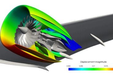
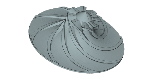
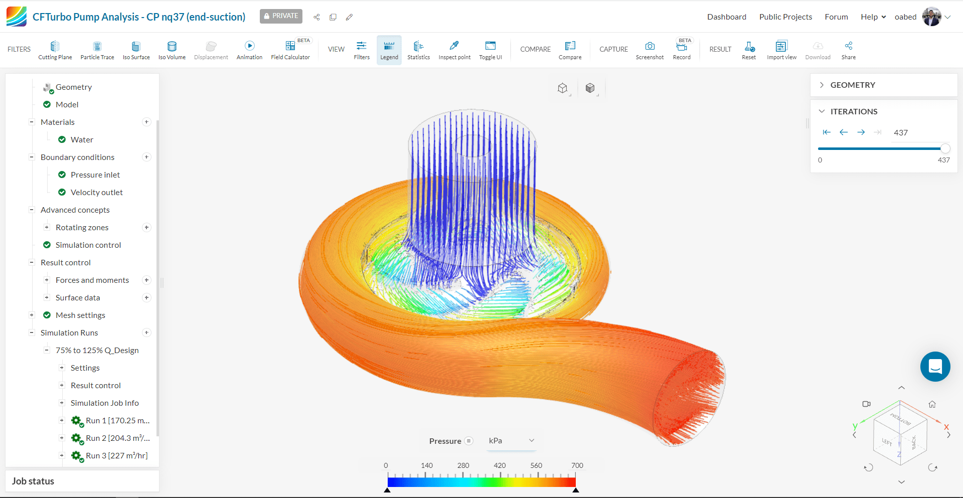
Engineers can benefit from a seamless workflow of CAD modeling and simulation using SimScale and CFturbo. This workflow enables faster turbomachinery modeling in the cloud by allowing engineers to seamlessly create CAD models of rotating machinery, such as impellers, in CFturbo and simulate them in SimScale to evaluate their blade profiles, pressure-flow characteristics, and efficiency requirements.
With scalable, high-performance computing and a binary tree-based mesher that allow for high-fidelity meshing and simulation, engineers can leverage the CFturbo-SimScale combined workflow to achieve fast simulation time, parallel simulation capabilities, stable simulation convergence, and high simulation accuracy—all in their favorite web browser; no hardware limitations and no installations are required.
With SimScale, engineers can:
- Optimize impeller designs faster by running several simulations simultaneously
- Use FEA and thermal analysis to test the stress and strain applied to pump impellers
- Get started quickly on an easy-to-use interface without extensive training
- Access cost-effective solutions and faster processing times
Cloud-Native Simulation for Industrial Machinery Manufacturing
Our latest eBook explores how cloud-native simulation is transforming industrial machinery manufacturing challenges into opportunities. Download it for free by clicking the button below.
Solving Cavitation Problems in Pumps
Cavitation is the formation of vapor bubbles inside a liquid with low pressure and high flow velocity. It is the leading cause of performance deterioration in pumps and turbines, significantly affecting impellers.
SimScale offers advanced simulation tools that allow engineers to model and analyze cavitation effects in pumps and turbomachinery. Using SimScale, engineers can:
- Conduct Comprehensive Analyses: Utilize computational fluid dynamics (CFD), structural (FEA), and thermal analyses through automated workflows and intuitive interfaces.
- Model Cavitation Phenomena: Understand the impact of cavitation on performance by simulating cavitating flow and studying parameters like the net positive suction head required (NPSHR), cavitation number, and inlet sizing.
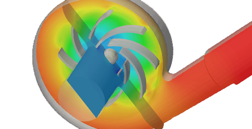
- Optimize Pump Efficiency: Use the Multi-purpose CFD solver to study and optimize pressure drop, fluid flow patterns, and cavitation effects. The solver’s robust meshing strategy ensures high-quality meshes and faster simulations.
- Import and Edit CAD Models: Easily import CAD models from various software and perform essential operations like flow volume extraction and defining rotating zones.
- Visualize Results: Leverage advanced visualization tools to analyze flow behavior, pressure distribution, velocity vectors, and cavitation effects.
Optimize Impeller Design With SimScale Cloud-Native Simulation
Are you seeking faster innovation and higher impeller design efficiency? SimScale offers a robust solution for reducing the time and cost associated with design and prototyping while maximizing accuracy and enhancing decision-making.
For engineers and designers aiming to push the boundaries of impeller design, SimScale provides the flexibility to explore innovative turbomachinery modeling. With SimScale’s integration with CFturbo, users can boost their impeller design modeling, benefiting from a seamless workflow that allows for faster and more accurate design and simulations.
SimScale’s advanced simulation capabilities enable you to test and validate innovative concepts that might be impractical or too risky to prototype traditionally. Experience the power of cloud-native simulation with SimScale. Sign up below and start simulating today.
Contributors: Muhammad Faizan Khan, Samir Jaber