Computational fluid dynamics (CFD) is an online application that assists the analysis and prediction of flow patterns, pressure distribution, and their interactions with counteracting flows, objects, and structures alike. This analysis, or simulation, works to evaluate digital replications of planned or existing designs, allowing for an iterative design process across virtually all industries.
In this article, we will examine how a digital replication or CAD model of the Vessel in New York City can be evaluated for pedestrian wind comfort using CFD, and more specifically wind comfort analysis from SimScale.
Wind Comfort Analysis from SimScale
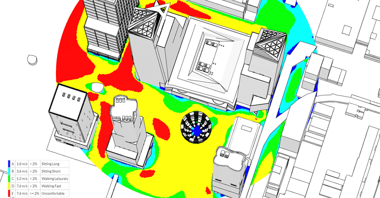
In 2019, we unveiled our new pedestrian wind comfort module that allows users to perform multi-directional wind analysis. Through creating a visual wind comfort map showing the different degrees of wind comfort—from blue (comfortable for long sitting) to red (uncomfortable), users can now evaluate and confer with different wind comfort standards around the globe including Lawson, Davenport, and NEN 8100. The animation below illustrates the results of a wind comfort simulation, where areas of discomfort appear in red around corners of buildings, as well as in the street where the skyscrapers have narrow streets between them.
This map provides a powerful plot to base design decisions on, enabling architects, urban development teams and municipalities to prevent issues that might arise after the project’s completion.
The Vessel, Hudson Yards, New York City
The Vessel in Manhattan, New York City is a newly built attraction for tourists and architecture enthusiasts alike. As part of the Hudson Yards Redevelopment Project, it stands 16 stories tall and is comprised of 2.5K steps in a captivating honeycomb-like shape. The total funding needed for the construction of the Vessel came to around $200 million.

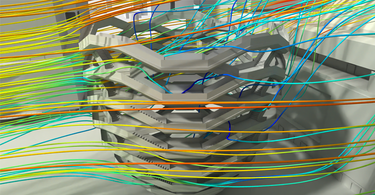
This SimScale project simulates the airflow and ultimately determines pedestrian wind comfort around the famous Vessel structure in New York City. The coloring of the flow lines represents the respective wind velocities, where blue is slow and red is high speeds. This can be seen in the two images below. The results, produced by a Lattice Boltzmann method (LBM) simulation on the cloud-based platform SimScale, are a valuable asset when designing such structure and integrating it into an existing environment.

One can note that the airflow accelerates as it enters the structure through the openings, a large part is diverted upward, as a result of a building located right behind it. In addition, the presence of this building in the immediate route of the airflow generates recirculation zones, where the air rotates down its facade to flow back up at the rear of the Vessel structure. This highlights a zone of potential issues for the comfort and safety of pedestrians on the ground but also at different heights such as the terrace shown as a recess in the facade. An aerial view of the Vessel and its surroundings can be seen pictured below:

This project exists as a great demonstration of SimScale’s wind comfort analysis abilities, as well as the level of CAD model sophistication that is able to be meshed and simulated on a cloud-based platform. For more information on this project and the Vessel itself check out this video from The B1M:
More Wind Comfort Resources from SimScale
- Lawson Wind Comfort Criteria: A Closer Look
- Wind Comfort Criteria: Lawson, Davenport, and NEN 8100
- How to Analyze Pedestrian Wind Comfort with SimScale
- Sustainable Wind Engineering: The Stockholm Royal Seaport Project


