Electric motors are vital electrical devices that power a wide range of applications by converting electrical energy into mechanical energy. From electric vehicles and industrial machinery to HVAC systems, robotics, and renewable energy systems, the versatility and energy efficiency of electric motors make them the preferred method of converting electrical energy into motion. To ensure the optimal design and performance of electric motors, engineers rely on simulation models that allow them to test, iterate, and optimize their design parameters under different conditions. Today, electric motor simulation is a common, if not essential, part of electric motor design.
In every electric motor application, design requirements, such as size, power, efficiency, and precision, can vary significantly, especially under different working conditions. Electric motor simulation and modeling provide a cost-effective and efficient method of testing and optimizing design parameters, predicting performance, and evaluating design alternatives without the need for expensive physical prototyping. This accelerates the design process, improves efficiency, and minimizes costs.
Today, electric motors have become indispensable in achieving optimal performance and energy conservation due to their efficiency, reliability, and precise control. In this article, we explore the working principle of electric motors, how they are designed, and how simulation tools can replicate real-world design conditions and help troubleshoot and optimize the design process.

How Electric Motors Work?
An electric motor is a device that converts electrical energy into mechanical motion. It operates on the principle of electromagnetism: When an electric current flows through a wire coil placed in a magnetic field, a force is exerted on the coil, causing it to rotate. This rotational motion is harnessed to perform useful work.
An electric motor consists of several essential components:
- Stator: The stator is the stationary part of the motor and consists of a core made of laminated steel sheets. It houses the wire coils, known as windings, which generate the magnetic field.
- Rotor: The rotor is the rotating part of the motor and is typically composed of a shaft and a set of laminated steel cores. The rotor rotates within the stator’s magnetic field and is responsible for producing the mechanical output.
- Windings: The windings are insulated wire coils wound around the stator. These windings are often made of copper or aluminum and carry the electrical current that creates the magnetic field.
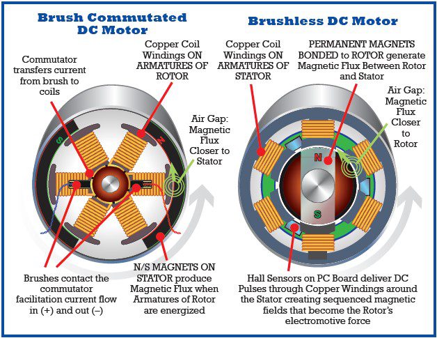
- Commutator (for DC motors): In DC motors, the commutator is a segmented cylindrical structure connected to the rotor. It plays a crucial role in reversing the direction of the electric current in the rotor windings, allowing for continuous rotation.
- Brushes (for DC motors): Brushes are conductive contacts that supply electrical current to the commutator, enabling the flow of electricity to the rotor windings.

Types of Electric Motors
Electric motors can be classified in several ways, such as “single-phase vs poly-phase” or “air-cooled vs liquid-cooled” electric motors. But the most prominent and prudent classification is based on the power source. Thus, we can classify electric motors broadly into DC and AC electric motors [2].
DC Electric Motors
DC motors are powered by direct current and are mainly of two types: brushed and brushless electric motors.
- Brushed DC motors use brushes mounted on the stationary stator of the motor. These brushes serve two purposes:
- To carry the necessary current required to create a magnetic field to the rotor, and;
- To ensure, with the help of a commutator, that the fixed magnetic field of the stator is in a continuous cycle of repulsion and attraction with the magnetic field generated in the rotor
- Brushless DC motors are constructed in reverse. The rotors have permanent magnets attached to them, and the stator has windings. The stator’s magnetic field is rotated via control electronics rather than mechanical commutation. Brushless DC motors are known for their improved efficiency, reliability, and reduced maintenance needs.
AC Electric Motors
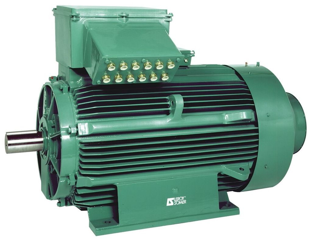
AC Electric motors are powered by an alternating current applied to the stator, which generates a magnetic field that interacts with another magnetic field in the rotor, causing rotation. There are also two main types of AC electric motors: synchronous motors and asynchronous motors (also known as induction motors).
- Synchronous AC motors have rotors that independently produce their own magnetic field (either via permanent magnets affixed to them or via a separate DC source), which interacts with the magnetic field of the stator to produce rotation. In these motors, the speed of the rotor is synchronized with the frequency of the alternating current that powers it and they are both linked immutably.
- Induction AC motors, also called asynchronous motors, have rotors with no magnetic fields of their own but have wire windings that are induced with a magnetic field from the magnetic field of the stator. The magnetic field of the stator and the induced magnetic field in the rotor interact to cause rotation. These motors have lower rotor speeds than the alternating current frequency; this difference is known as ‘slip’. The torque of the motor is proportional to this slip.
The Theory behind Electric Motors
Electric motors work based on the relationship between an electric current and the magnetic field it generates when passing through a conductor. Important formulas in expressing this relationship include Coulomb’s Law, Ampere’s law, Faraday’s law of induction, and Lenz’s law.
Coulomb’s Law
Coulomb’s law states that the force of attraction or repulsion \(F\) between two charges, \(q_1\) and \(q_2\), is directly proportional to the product of the quantities of each charge and inversely proportional to the square of the distance \(d\) between them:
$$ F = k_e \frac{q_1 q_2}{d^2} $$
Where \(k_e\) is the electrostatic constant.
This tells us that there is a force between two charges interacting with each other, be they similarly or oppositely charged.
Ampere’s Law
Ampere’s law indicates that an object of length \(l\), carrying an electric current \(I\) creates a magnetic field \(B\) around it. It is expressed as:
$$ \int{B.dl} = \mu_0 I $$
Where \(\mu\) is the permeability constant.
Faraday’s Law
Faraday’s law of induction states that the induced electromotive force in a coil \(\epsilon\) is directly proportional to the negative of the change of magnetic flux \(\Phi_B\) over time \(t\):
$$ \Phi_B = -N \frac{d\Phi_B}{dt} $$
Where \(N\) is the number of loops in the coil.
This allows us to predict the strength of an electromotive force given the rate of change in the magnetic flux and the number of winding coils on a conductor. The negative sign indicates that the direction of the electromotive force is opposite to the direction of the rate of change of the magnetic flux. This principle is known as Lenz’s law, and its expression is identical to that of Faraday’s law, albeit with a different focus.
These fundamental formulas allow us to understand how electromagnetism works and consequently, how an electric motor works. These were brought together into Maxwell’s equations and are used in electric motor simulation and design to model the electromagnetic phenomena taking place. Other types of engineering simulation are also used to simulate the physical properties of the electric motor and how they interact with each other while the electric motor is in operation. These include structural mechanics simulation and thermal analysis.
Electric Motor Simulation and Design using SimScale
Engineering simulation enables engineers to virtually recreate and study motor behavior under various operating conditions. It provides insights into performance, efficiency, and potential design improvements, saving time and resources compared to traditional trial-and-error methods. By simulating motor performance, engineers can evaluate different design options, identify potential issues, and fine-tune motor parameters to achieve optimal performance. It allows for the exploration of various scenarios and helps in making informed decisions to enhance motor efficiency, reliability, and overall performance.
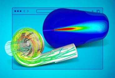
As a cloud-native simulation platform, SimScale offers a comprehensive range of tools for simulating and optimizing electric motors without any hardware or software limitations. All simulations can be run online directly in a web browser. These include electromagnetic simulation, thermal simulation, and structural analysis.
Electromagnetic Simulation of Electric Motors
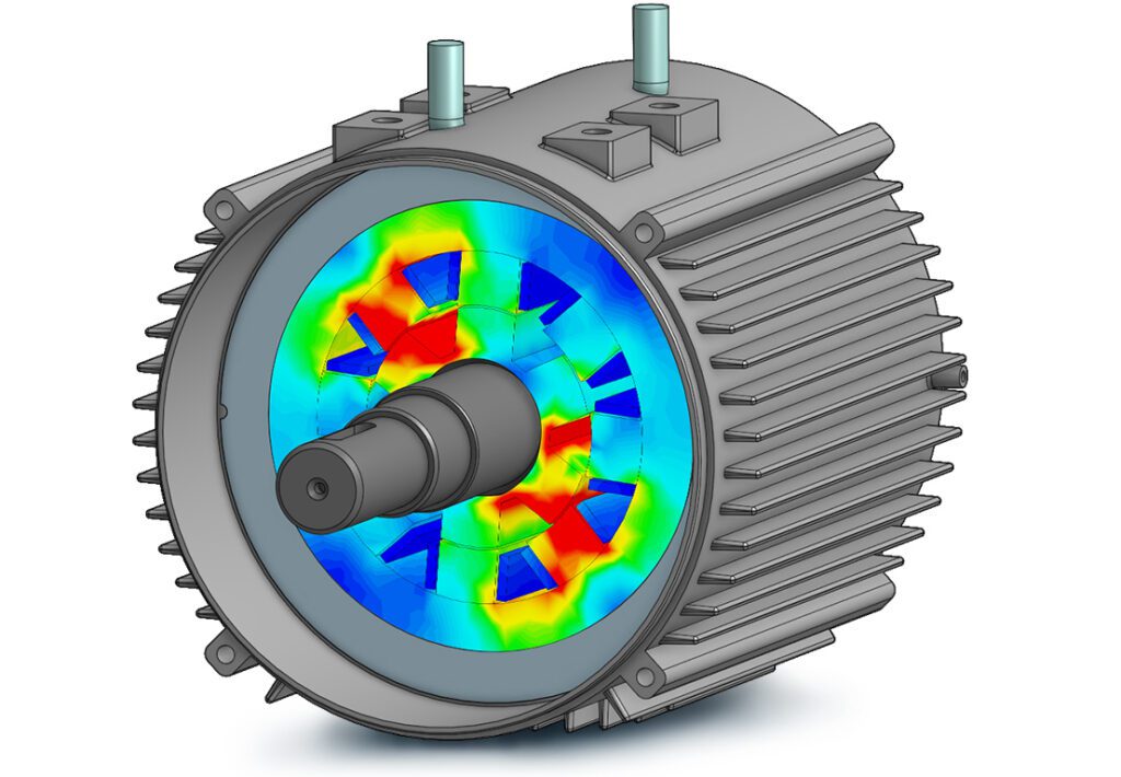
EM simulation uses magnetostatics, time-harmonic magnetics, and electrostatics simulation features to visualize and analyze electromagnetic parameters and study their interaction in an electric motor during operation. This gives the designer valuable insight into torque generation and ripple effects and how to potentially reduce inefficiencies due to slip or other design flaws. It also helps in selecting the correct magnetic and conductor materials that work best together to achieve the highest efficiencies.
Using SimScale’s electromagnetic simulation solver, engineers can analyze the following:
- Magnetic Field Analysis: SimScale provides tools to analyze the magnetic fields generated by electric motors. This includes both static and transient simulations.
- Eddy Current Analysis: Users can simulate eddy currents to evaluate losses and heating effects in the motor components.
- Torque Calculation: Users can calculate the torque produced by the motor under various operating conditions.
- Inductance and Resistance Calculation: Users can determine the inductance and resistance of motor windings, essential for understanding the motor’s electrical characteristics.
Thermal Simulation of Electric Motors
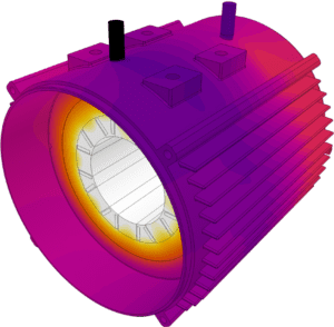
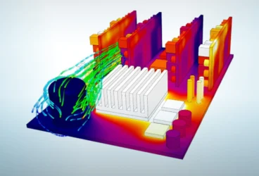
Thermal analysis uses thermal simulation tools to visualize the forms of heat transfer: conduction, convection, and radiation in an electric motor. It enables engineers to design and test cooling systems, find ways to mitigate excessive heating, or design easier and quicker heat distribution and dissipation. This can minimize energy losses and maximize the motor’s efficiency and lifespan.
Using SimScale’s thermal analysis tool, engineers can study the following aspects:
- Heat Transfer Analysis: SimScale allows users to perform thermal simulations to evaluate the temperature distribution within the motor, ensuring that the motor operates within safe temperature limits.
- Cooling System Design: The platform can be used to design and optimize cooling systems, such as air or liquid cooling, to effectively manage heat dissipation.
Structural Analysis of Electric Motors
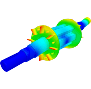
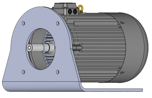
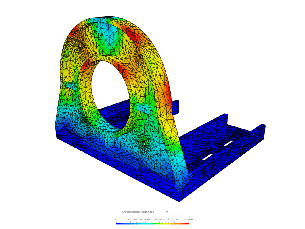
In addition to studying the electromagnetic and thermal phenomena in an electric motor, engineers can couple those with analyses of the motor’s structural integrity. This includes stress and vibration analyses, where users can leverage SimScale’s structural mechanics simulation capabilities to analyze the mechanical stresses and vibrations experienced by the motor components during operation, helping to ensure structural integrity and longevity.
This makes use of Finite Element Analysis (FEA) to simulate the physical properties of the parts of an electrical motor, the mechanics of its operation, and the effects of this operation on the properties of the motor parts. FEA can give an engineer valuable insight into the mechanical behavior and structural integrity of an electric motor and help evaluate areas of deformation or weak spots, highly stressed areas, and sources of vibration.
Cloud-based Parametrization, Optimization, and Collaboration
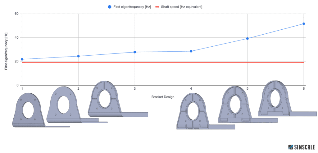
By leveraging the cloud, SimScale offers unparalleled levels of optimization and parametrization, enabling engineers to reduce their simulation time from days and weeks to hours and minutes. To understand the impact of different design variables on motor performance, users can conduct parametric studies and run as many simulations as needed in parallel without compromising the quality of the results or being limited by local hardware constraints. This allows for efficient shape and design optimization to reach the optimal design under the electric motor’s operational conditions.
SimScale also supports easy and quick collaboration by streamlining the ability to share simulation projects with team members and stakeholders. In other words, team members can access simulation projects anywhere by simply accessing the corresponding URLs. This enhances collaboration and feedback, accelerates design innovation, and allows for enterprise-wide deployment of simulation.
By leveraging SimScale’s comprehensive simulation capabilities, engineers can efficiently optimize electric motor designs, enhancing performance, efficiency, and reliability while reducing development time and costs.
Electric Motor Simulation: Start Simulating Now
The design phase of any product often requires multiple design iterations to achieve every possible performance improvement. Using SimScale’s FEA, EM, and Thermal simulation tools, cloud-native simulation allows for iterations of design changes to be carried out relatively stress-free.
SimScale offers simulation with an assortment of cutting-edge proprietary and open-source solvers, which have been incorporated into SimScale’s cloud-native computing interface to be able to run multiple electric motor simulations in parallel rather than one at a time. All this can be done within a web browser with a user-friendly interface without the need for any expensive and cumbersome hardware.
You can start simulating right away on the SimScale platform straight from your favorite web browser without any need for software installation or hardware required.
References
- Hughes, A. (2005). Electric motors and drives: fundamentals. Elsevier Science & Technology.
- Moyer, E. J., & Chicago, U. (2010). Basics on electric motors. University of Chicago.
Contributor: Olawale Olayemi
