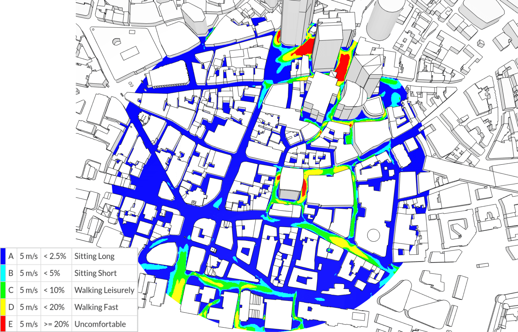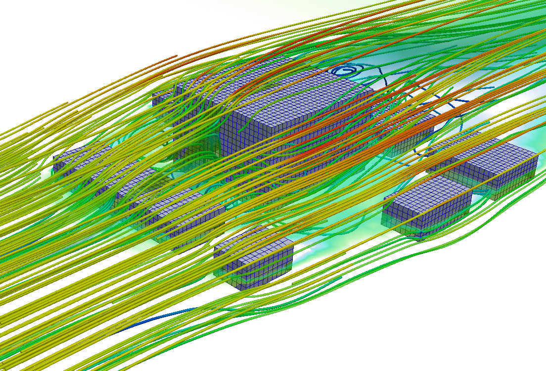

A wind engineer’s job is to answer questions the wind climate poses about a building that does not exist yet, using data from a weather station that is nowhere near it. That translation, from a met record kilometers away to a pressure on a facade or a wind speed at a bus stop, is what the discipline exists to do. It is also where most of the error accumulates.
This page covers the discipline, the work it produces, the scales it operates across, and what the recognized guidelines specify for a CFD setup.
What is wind engineering?
Wind engineering is the analysis and mitigation of wind effects on the built environment and the people in it. It combines structural dynamics, fluid dynamics, meteorology and statistics. Its outputs range from a cladding pressure to a chapter of a planning application.
The term was coined in 1970, and the discipline is generally traced to the UK in the 1960s. Three moments shaped it. The 1879 Tay Bridge collapse established wind as a structural design case rather than an act of God. Martin Jensen’s 1958 model law gave the field its experimental method, by establishing that the approach flow profile has to be matched to reality. And the World Trade Center towers in the mid-1960s turned it into a profession, because nothing that slender had been built before.
Wind engineering is not wind energy engineering
These get conflated constantly, including by search engines. Wind engineering concerns wind effects on structures and urban spaces: loads, pedestrian conditions, ventilation, dispersion, noise. Wind energy engineering concerns extracting power from wind: turbine design, resource assessment, farm layout, IEC 61400 site classification. This page is about the first.
They share a fluid-dynamics foundation and occasionally a practitioner. Beyond that the standards, deliverables and clients diverge completely. If you are reading about turbine gearboxes, you are in the other field.
What a wind engineer actually does
The work is a chain, and every link can dominate the error budget.
It starts with the wind climate: long meteorological records reduced to a directional distribution, then translated to the site through terrain roughness and exposure. Practice assesses up to 36 wind directions. It ends with a document a planning authority, a structural engineer or a facade contractor can act on.
Between those two points:
- Deriving site wind statistics and translating station data to site conditions
- Building the subject geometry plus its surroundings, and running the direction set
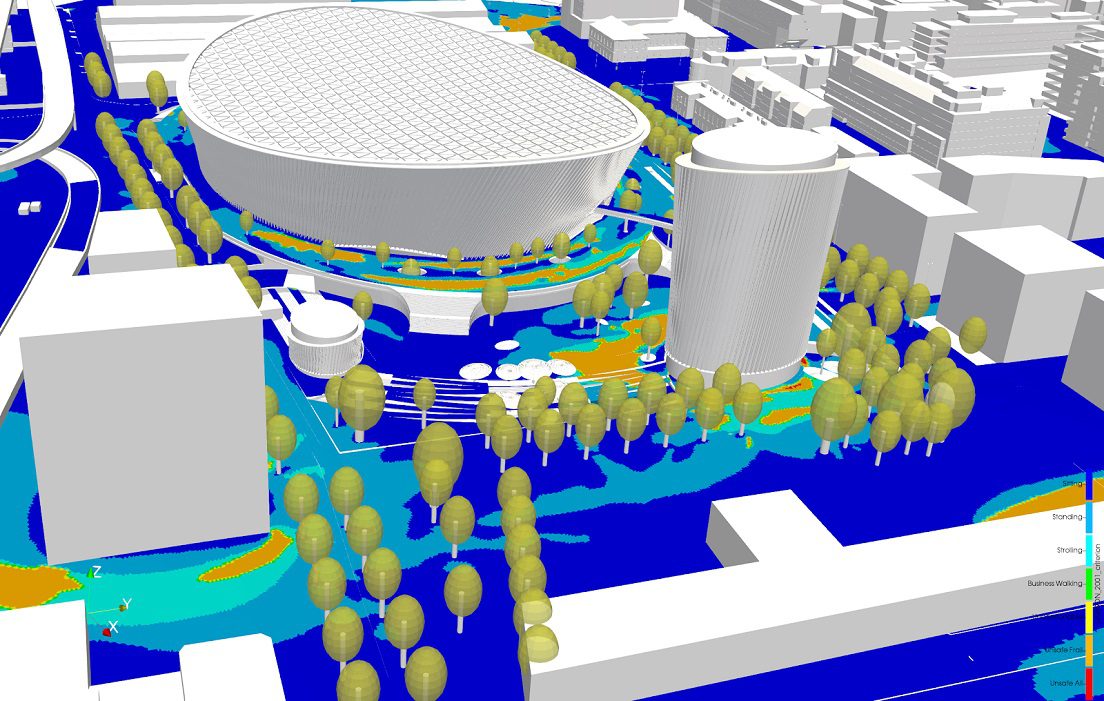
- Assessing pedestrian and cyclist conditions against a comfort and safety criterion
- Determining wind loads and pressures for structure and cladding, and the dynamic response that goes with slenderness
- Aerodynamic shape work: corner treatments, tapering, setbacks, porosity
- Wind-induced noise from facade features, screens and rooftop plant
- Natural ventilation, air exchange, pollutant dispersion, wind-driven rain
- Snow drifting, and wind on rooftop plant, solar arrays and temporary works
- Forensic work after an event: damage investigation and probabilistic high-wind risk
The deliverables
| Deliverable | What it contains | Who consumes it |
|---|---|---|
| Wind study report | Methodology, wind climate, results, compliance statement | Planning authority, client |
| Pedestrian comfort map | Category classification at 1.5 to 1.75 m, per season | Planner, landscape architect |
| Cladding pressure zones | Design pressures by facade region | Facade contractor |
| Structural loading set | Base shear and moment, dynamic response, accelerations | Structural engineer |
| Mitigation recommendations | Massing, canopy, screen and planting changes | Architect |
| ES wind chapter | The wind section of an Environmental Statement | Planning submission |
Who does this work
Specialist wind consultancies, the wind teams inside multidisciplinary engineering firms, forensic and risk consultancies, building science testing bodies, and university labs. Increasingly also in-house teams at large architecture practices and facade contractors, which is the shift cloud simulation has enabled.
The professional bodies are the International Association for Wind Engineering and its national members, including the American Association for Wind Engineering. The field publishes in the Journal of Wind Engineering and Industrial Aerodynamics, and the International Symposium on Computational Wind Engineering reaches its eighth edition in 2026.
The value of a wind engineer is highest before building volumes and orientations are fixed. After that point, findings turn into retrofits, and a retrofit is a screen or a canopy bolted onto a finished building.
What computational wind engineering is
Computational wind engineering is the use of CFD for wind engineering problems, together with the validation and measurement practice that makes the results usable. It has moved from a research activity to mainstream practice across six decades, and it now sits alongside boundary-layer wind tunnel testing rather than replacing it.
The two methods answer to different authorities. Boundary-layer wind tunnel testing is explicitly recognized in code, with test conditions governed by ASCE 49. CFD is standard practice for pedestrian-level conditions, microclimate and ventilation, and in some jurisdictions explicitly accepted for them, but ASCE 7 does not list computational methods among its permitted procedures for wind load determination. SimScale has written about that boundary in detail.
A side-by-side comparison of cost, lead time and what each method gives you sits in the wind analysis guide.
The spatial scales, and why they decide your model
Wind engineering spans five orders of magnitude, and you never model all of them. The skill is picking the band your question lives in, resolving that, and assuming the rest.
| Scale | Range | What it contains | How it enters your model |
|---|---|---|---|
| Synoptic and mesoscale | 10s to 100s of km | Weather systems, pressure gradients | Ingested as long-record wind statistics |
| Regional / terrain | 1 to 20 km | Topography, upwind roughness, exposure category | Profile shape plus ground roughness; resolved geometry only for strong topography |
| Urban / neighborhood | 100 m to 2 km | The surrounding built form that channels and shelters | The resolved outer domain. Simplified blocks are fine |
| Building | 1 to 100 m | Massing, podium, corners, canopies, openings | Where the mesh budget goes |
| Component | under 1 m | Louvers, mullions, railings, roof plant | Defeatured, or represented as porosity |
Which way you move depends on the question. Air exchange in one building inside an irregular block forces you up a scale, because the inlet velocity at the opening stops being something you can assume. Ground-level flow on flat open terrain lets you drop down one, because internal layout only costs cells.
The largest error source in most studies sits at the top of that table. A met record gathered over different terrain some distance away has to be translated to the site before it means anything, and that translation carries more uncertainty than the mesh does. Resolving the building to a millimeter will not fix it.
What the CFD guidelines actually prescribe
Three frameworks are recognized in practice, and between them they answer most setup arguments. What follows is what each one specifies.
COST Action 732, Best Practice Guideline for the CFD Simulation of Flows in the Urban Environment (Franke, Hellsten, Schlünzen and Carissimo, 2007), produced under the COST action on quality assurance of microscale meteorological models. Focused primarily on steady RANS.
The AIJ guidelines (Tominaga and colleagues, JWEIA 96(10), 2008) for the pedestrian wind environment, with a companion volume by Tamura and colleagues covering wind loads that does treat LES, because peak quantities need time-dependent analysis. The AIJ guidelines come with a published benchmark suite, Cases A to G, with wind tunnel data for validation.
The City of London Wind Microclimate Guidelines (2019), the UK’s first local-authority planning wind guidance, which assesses against the Lawson and LDDC categories. Worth knowing before you plan a study: above 100 m the guidelines call for a wind tunnel study and a CFD study, by independent consultants, specifically so the CFD cannot be tuned toward a known answer. SimScale has covered compliance with those guidelines separately.
Domain sizing and mesh
Where H is the height of the tallest building:
| Parameter | COST 732 | AIJ |
|---|---|---|
| Upstream | 5H (approach profile known) | 5H |
| Downstream | 15H | at least 10H |
| Lateral | 5H from the building | 5H or more |
| Top | 5H | 5H or more |
| Blockage ratio | under 3% | not stated in the pedestrian guideline |
| Inflow profile | Log law, Richards and Hoxey | Power law, terrain-dependent exponent |
| Lateral and top boundary | Constant shear stress matching inflow | Free-slip / inviscid wall |
| Cells across a building side | not specified | at least 10 |
| Cell expansion ratio | 1.3 or less | 1.3 or less |
| Pedestrian evaluation height | not specified | 1.5 to 5.0 m, at the 3rd cell or higher |
Two of those deserve explanation.
The 3% blockage limit exists because an undersized domain forces flow over the building when it should be going around. Detour flow is most of the answer at ground level, so a domain that suppresses it returns a result that looks plausible and is wrong exactly where it matters.
The downstream extent is the one people cut to save cells, and it is the one that governs wake redevelopment. COST asks for 15H, AIJ for at least 10H. An outflow boundary sitting inside a recirculation region is being asked to do physics it was never specified for.
One near-wall point the guidelines do carry, and that generic y+ advice misses: with sand-grain roughness wall functions, the governing constraint on the ground is the first-cell height against the equivalent sand-grain roughness, not a y+ band. Getting that pairing wrong is the usual cause of the profile decay described below.
The horizontal homogeneity requirement
Both frameworks require the specified inlet profile to survive the journey to the building. The test is an empty-domain run with the same inlet and ground conditions: if the profile decays before reaching the building position, the building is being hit by a different wind than the one you specified, and the usual cause is an inlet profile and a wall function that do not correspond.
This is a requirement rather than good practice, and it is the check most often skipped.
Which turbulence model, and what breaks
Steady RANS with a two-equation model remains the practical default for mean quantities. It has two long-documented failure modes for bluff bodies, summarized in Blocken’s review of the field:
The stagnation-point anomaly. Standard k-epsilon overestimates turbulent kinetic energy near the frontal corner, which underestimates the size of separation and recirculation regions on the roof and side faces.
The wake defect. The same model underestimates turbulent kinetic energy in the wake, which overestimates the size of the cavity zone and the wake itself.
Both trace back to the same structural limitation: steady RANS cannot represent the inherently transient features of the flow, including separation and recirculation downstream of windward edges and vortex shedding in the wake. Revised k-epsilon variants improved local regions and left that limitation in place.
| Model | Use it for | Known weakness |
|---|---|---|
| Standard k-epsilon | Cheap mean pedestrian-level speed | Stagnation-point anomaly, wake defect |
| RNG k-epsilon | Better separation response than standard | Still steady RANS |
| Realizable k-epsilon | The preferred k-epsilon variant for rotation, separation and recirculation | Still steady RANS |
| k-omega SST | The general first choice for separating bluff-body flow | Modest cost premium over k-epsilon |
| Reynolds Stress Models | Anisotropy, streamline curvature, secondary flows | Expensive, numerically stiff, poor convergence |
| LES | Peak and time-dependent quantities | An order of magnitude more expensive; time-dependent inlet and wall conditions are hard |
| Hybrid DES / DDES | LES fidelity at reduced cell count | Interface treatment between zones |
The cost argument behind model choice has moved
The standard verdict a decade ago was that LES stayed out of reach for practical pedestrian-level studies in real urban environments. That held for finite-volume LES on CPUs. Lattice-Boltzmann methods on GPUs have since made hybrid LES routine at district scale.
How close any of these models gets to measured data is a validation question, and SimScale’s validation work against the AIJ benchmark cases covers it with the numbers.
Where to start
The guideline table above comes first. Domain extents, blockage ratio and cell count across the building are decided before anyone opens a mesher, and refining later does not recover a domain that was sized wrong.
One scoping consequence worth knowing: the frameworks treat the subject building and its surroundings differently. The subject carries the detail and the cell budget. Neighboring buildings are represented as simplified blocks. Terrain roughness beyond the resolved domain enters through the inflow profile rather than as geometry.
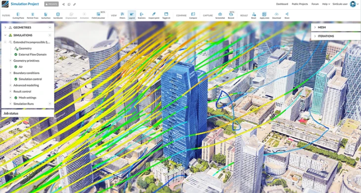
SimScale covers the chain the guidelines describe: atmospheric boundary layer inflow, the full direction set in parallel, LBM and finite-volume solvers, and facade-level result extraction. Explore wind simulation on SimScale or start a free account.
Where to go next, depending on your question:
- Pedestrian-level conditions and validation against wind tunnel data: pedestrian wind comfort validation
- Wind loads, ASCE 7 and Eurocode procedures: wind load analysis
- Which type of wind study you need: the wind analysis guide
- The named flow effects around buildings: building aerodynamics and wind effects
Run a wind engineering study in the browser
Atmospheric boundary layer inflow, the full direction set in parallel, and facade-level results. No hardware to provision.
Frequently asked questions
The analysis and mitigation of wind effects on the built environment and the people in it. It draws on structural dynamics, fluid dynamics, meteorology and statistics to predict wind loads, pedestrian-level conditions, ventilation, dispersion and wind-induced noise. The term was coined in 1970 and the discipline emerged in the UK in the 1960s.
No. Wind engineering concerns wind effects on buildings, bridges and urban spaces. Wind energy engineering concerns turbines, resource assessment and farm layout. They share a fluid-dynamics foundation and very little else: different standards, different deliverables, different clients.
Derives site wind statistics from meteorological records, models the building and its surroundings across up to 36 wind directions, and produces the assessments a project needs: pedestrian comfort classification, cladding and structural pressures, ventilation and dispersion results, and mitigation recommendations. The output is a report a planning authority or a structural engineer can act on.
The use of CFD for wind engineering problems, with the validation and measurement practice that makes the results usable. It has grown from research into mainstream practice across six decades and now sits alongside boundary-layer wind tunnel testing.
Three are widely recognized: COST Action 732 (Franke and colleagues, 2007) for urban flows, the AIJ guidelines (Tominaga and colleagues, 2008) for the pedestrian wind environment with a published benchmark suite, and the City of London Wind Microclimate Guidelines (2019) at planning level.
COST 732 specifies 5H upstream, 15H downstream, and 5H laterally and above, where H is the height of the tallest building. The AIJ guidelines specify 5H or more laterally and above, with the outflow boundary at least 10H behind the building.
COST 732 requires the projected facade area against the inlet boundary area to stay below 3%. Above that, the domain forces flow over the building rather than around it, which distorts the detour flow that governs ground-level results. The AIJ pedestrian guideline does not state a figure, so COST’s 3% is the working limit.
The AIJ guidelines require at least 10 cells across one side of a building, and that the 1.5 to 5.0 m evaluation height sits at the third cell or higher above ground. Both frameworks cap the cell-to-cell expansion ratio at 1.3. On the ground, with roughness wall functions, the binding constraint is the first-cell height against the equivalent sand-grain roughness rather than a y+ target.
For steady RANS, k-omega SST is the general first choice for separating bluff-body flow, with realizable k-epsilon the best k-epsilon variant. Standard k-epsilon stays common for mean pedestrian-level speed because it is cheap and converges reliably. Use LES or a hybrid such as DDES when peak or time-dependent quantities matter.
Two documented failure modes. Standard k-epsilon overestimates turbulent kinetic energy near the frontal corner, underestimating separation and recirculation on the roof and side faces. It also underestimates turbulent kinetic energy in the wake, overestimating the cavity and wake size. Underneath both, steady RANS cannot represent transient behavior such as vortex shedding.
Yes. The AIJ guidelines ship a benchmark suite, Cases A to G, with wind tunnel data, so a solver’s claims can be checked against a common reference rather than taken on trust. SimScale’s results against those cases are published in the pedestrian wind comfort validation study.
References
- Franke, J., Hellsten, A., Schlünzen, H., Carissimo, B. Best Practice Guideline for the CFD Simulation of Flows in the Urban Environment. COST Action 732, 2007.
- Tominaga, Y. et al. AIJ guidelines for practical applications of CFD to pedestrian wind environment around buildings. Journal of Wind Engineering and Industrial Aerodynamics 96(10), 2008.
- Tamura, T. et al. AIJ guide for numerical prediction of wind loads on buildings. 2008.
- Blocken, B. 50 years of Computational Wind Engineering: Past, present and future. Journal of Wind Engineering and Industrial Aerodynamics, 2014.
- City of London. Wind Microclimate Guidelines for Developments in the City of London. 2019.
- ASCE/SEI 49, Wind Tunnel Testing for Buildings and Other Structures.