When dealing with turbomachinery, for instance compressors, propellers, or pumps such as a centrifugal pump, the slightest design change can have a huge impact. Depending on the machine, even a one percent improvement in efficiency could lead to a cost saving of thousands of dollars over the course of the machine’s lifespan.
A turbomachine transfers energy between a rotor and a fluid. In this way, mechanical energy is converted into pressure or head. Usually in turbomachinery design, an engineer’s main goals are efficiency, reliability, performance, and extended lifespan. Roughly put, a machine should perform as well as possible, for the longest time possible, efficiently recover as much energy as possible, and require as little maintenance as possible. While these factors are in the direct interest of manufacturers, suppliers, and customers, additional considerations such as noise pollution or emissions output are increasing in importance due to tightening regulations on environmental impact and an increased demand for comfort. All of these aspects require careful calculation in the design phase.
Turbomachinery Design Our Case: Centrifugal Pump Design with CFD
As an example of turbomachinery, this case simulates a common pump type; a centrifugal pump. This type of pump converts rotational energy into energy in a fluid via a rotating element. In the aim of maximizing efficiency, it is crucial to reduce loss of energy in order to ensure that the machine is harnessing as much power as possible. Energy losses could occur, for example, due to friction or recirculation. Computational fluid dynamics, or CFD, makes it possible to quantify performance in the form of torque, axial thrust, pressure drop, and velocity of flow at any point inside the domain to identify areas that could be optimized for efficiency.
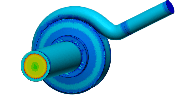
There are many design aspects that can affect the efficiency of a pump such as casing, shrouding, number of impeller blades, or blade angle, to name a few. Focusing on the impeller, changes could be made to its size, such as by increasing diameter , however this would increase mass and therefore lead to greater energy loss. Trying to find the trade-off between impeller size and mass presents a challenge to engineers seeking maximum efficiency.
In the case of the centrifugal pump design with a central impeller, CFD is a beneficial tool in analyzing efficiency. Using CFD an engineer can analyze the performance of a design, easily changing parameters to see how flow is affected and creating a pump curve for efficiency.
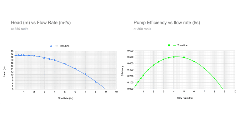
With CFD, it is much simpler and faster to try to find the most efficient design based on the best scenario at a specific speed. Simulating designs allows for fluid flow analysis without the need for physical prototyping, which can consume both time and cost.
Cloud-Native Simulation for Industrial Machinery Manufacturing
Our latest eBook explores how cloud-native simulation is transforming industrial machinery manufacturing challenges into opportunities. Download it for free by clicking the button below.
Simulation Setup
The simulation was set up using an incompressible, steady-state analysis with a K-Omega SST turbulence model. This type of analysis is robust and well-suited to applications with rotating components. Where some pumps may be used for substances such as oil, sewage, or food and beverages, this pump will be used for water and so the fluid type selected was water at 20°C.
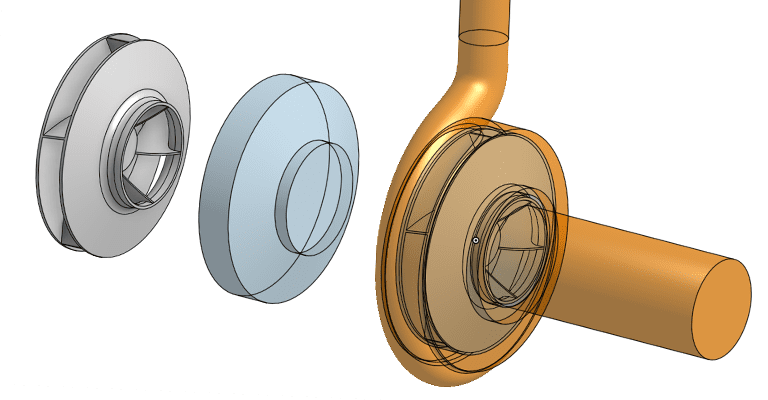
For this project, the geometry was imported as three volumes; the impeller volume, a volume for the rotating region, and the fluid flow volume. The part that could be considered the most challenging is the impeller itself as it is constantly rotating. For this reason, the additional volume of the rotating zone is included and a multi-reference frame method (MRF) applied.
The MRF method is a simple and less computationally demanding way to analyze the behavior of a rotating element without having to rotate the geometry in a simulation. It gives a reliable approximation of transient rotating motion at an instance of time. For this analysis, the angular rotational velocity of the rotating zone is set to 350 rad/s. The inlet is inputted as a volumetric flow rate of 0.004 m3/s, a parameter that can be easily changed to simulate different operating conditions, in parallel runs. And the outlet face has its pressure set at 0 Pa, which can be monitored, alongside the inlet face for both average and integral results.
Results
The results of this CFD analysis reveal many opportunities for design optimization. In particular, certain changes in velocity and pressure demonstrate areas where energy is lost. The flow velocity pattern of this analysis shows a few key areas where energy is lost. Flow velocity clearly diminishes past the cutwater, and flow recirculation occurs around the eye of the impeller. This recirculated fluid does not contribute to pump performance, and adjustments should be made to recover this lost energy, such as changes to the shroud geometry.
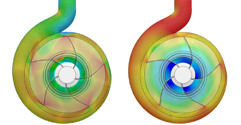
As fluid enters the spiral volute of a pump, it is transformed into pressure energy. In the ideal design, the pressure increase experienced in this region is smooth and gradual. In the initial run of this design however, there is a sudden decrease in velocity at the beginning of the spiral volute. This is sure to negatively impact the efficiency of the pump and should be reviewed.
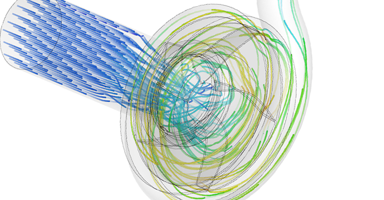
Taking a closer look at the particle traces simulation, flow vortices can be seen at the entrance of the pump, a common phenomenon that uses up energy without contributing to power output. In this case, the impeller rotation is inducing a vortex at the inlet. To limit this effect, the engineer could decide to include fins in the pump housing to create a more efficient design.
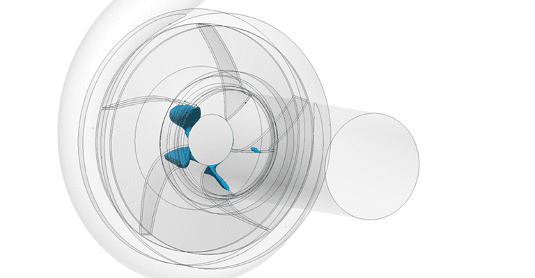
The isosurface results reveal valuable insights for performance optimization. Extremely low pressures in the corners of the impeller blades, close to the eye, suggest the risk of pump cavitation. Pump cavitation not only represents wasted energy consumption, but can also cause significant damage and premature failure of the impeller and surrounding components. Excessive noise also becomes an issue in this case due to shockwaves.
Centrifugal Pump Analysis Conclusion
This simulation demonstrates how useful CFD can be in identifying areas in a design that negatively impact on efficiency. Using results such as these, an engineer can make informed design decisions to optimize a turbomachinery design for improved overall performance, reliability, and value—all from the comfort of their web browser.
If you are interested in finding out more information surrounding this topic, make sure to check out the following:
- Introduction to Pumps & Water Turbines
- Turbomachinery Pump Curves
- Simulating Rotating Zones with MRF
- Public Project: Simulation of Centrifugal Pump
