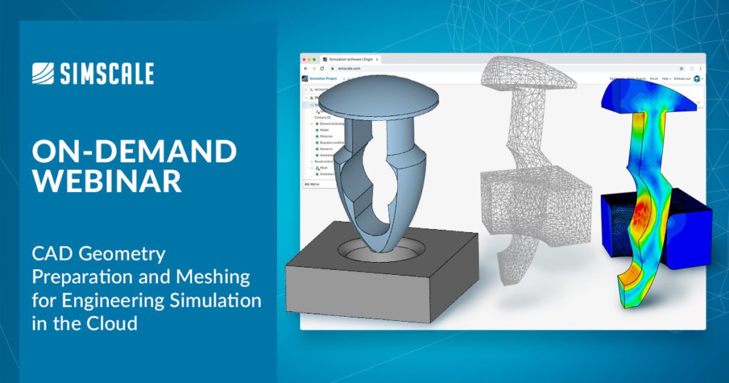
Preparing, uploading, and adapting CAD geometry for analysis is the first step in setting up any three-dimensional simulation for analysis. SimScale is a cloud-native simulation tool with accessible CAD import and cleanup features that empower engineers and designers to overcome common bottlenecks and spend more time simulating and creating valuable design insights. Another aspect of simulation that engineers often report as tedious and less than straightforward is meshing. Again, SimScale offers robust and automatic meshing for most analysis types, utilizing fast and fit-for-purpose discretization schemes with added refinement and control for advanced users.
SimScale supports the most common geometry formats for importing CAD, including Solidworks®, Inventor®, STEP, IGES, STL, and Parasolid®. Third-party CAD connector apps are available for Onshape® and other tools, allowing seamless integration. Furthermore, the native application programming interface (API) in SimScale, with both a Python and C SDK, amplifies the ability to customize CAD workflows and connect or control third-party tools. In this article, we have used a 3D model of a support bracket to introduce the integrated 3D CAD and meshing tools in the SimScale platform. Continue reading and watch our on-demand webinar, CAD Geometry Preparation and Meshing for Engineering Simulation in the Cloud to learn how to source and import 3D CAD models, clean geometry by using internal CAD mode editing features in SimScale, and apply various meshing settings to make the model simulation ready in a few simple steps. With new features continuously added, CAD mode supports operations like scaling, extrude, body and face delete, surface splitting, etc. Engineers can use CAD mode associativity with Onshape and other third-party tools to streamline parametric studies from a baseline CAD model, a powerful feature further enhanced by parallel simulation in the cloud.
Simulation-Ready CAD
After CAD upload, additional preparation might be required depending on how the file has been created. SimScale offers a dedicated environment to interact with your model called CAD mode that helps users prepare the model within SimScale without switching to external CAD software. CAD mode supports operations like scaling, extrude, body and face delete, surface splitting, flow volume extraction, etc., with continuously adding new features.
The CAD mode feature in the SimScale platform offers a set of purpose-built CAD editing and simplification tools. For example, the Flow Volume Extraction operation alleviates engineers from laboriously isolating a flow volume as required in other pre-processing systems. Unlike traditional CAD systems, CAD mode focuses on a core set of simple, intuitive, versatile tools ideal for making CAD models simulation-ready. CAD Mode is used to interact with a CAD model, delete, extrude, or scale CAD parts, and perform CAD-related operations directly within the platform. Any gaps or interferences in a 3D model can be automatically identified using CAD mode, which is also used to fix these issues. Preparing, uploading, and adapting your CAD model for analysis is the first step in setting up a simulation. CAD file associativity between varying CAD files is applied automatically in SimScale, maintaining naming conventions for parts/faces from the original CAD model. This means that when swapping CAD files for comparative studies, users do not have to reassign boundary conditions, mesh settings, or result control outputs, making comparing two or more CAD variants of a single product much faster.
The full list of supported CAD formats:
- SolidWorks (.sldprt, .sldasm)
- Autodesk Inventor (.iam, *.ipt)
- Rhino® 4, 5, 6, and 7 (.3dm)
- CATIA (.CATPart, .CATProduct)
- PTC Creo® (.prt, .asm)
- Siemens NX™ (.prt)
- Solid Edge (.par, .asm, .psm)
- Revit® (.rvt)
- Neutral formats: Parasolid (.x_t, .x_b), ACIS (.sat, .sab), STEP (.stp, .step), IGES (.igs, .iges), STL (.stl)
- CAD Plugins
- SimScale Connector App for Onshape
- SimScale Plugin for Solidworks
- SimScale Integration for Autodesk® Fusion 360™
- Grasshopper
- SimScale CAD Mode

Quickly Mesh & Solve Complex Designs
Mesh generation has been a labor-intensive and tedious aspect of traditional CFD software. The SimScale platform is based on a unique meshing technique that ensures the mesh is robust enough to apply to many types of CAD models the first time around. A bespoke meshing technology is harnessed to generate meshes quickly for complex geometries. Engineers can mesh and simulate models with an easy-to-use and intuitive workflow. SimScale strives to make the meshing process as simple and user-friendly as possible. A user should only have to decide on the trade-off between mesh fineness and the required computational resources (number of processors assigned). Due to the robustness and general applicability of the meshing algorithms in SimScale, both automated and manual options are provided. Unlike traditional simulation software, meshing is the second step in the simulation setup after geometry upload. SimScale delays the meshing action until all other steps are completed so engineers do not waste time waiting for mesh generation. Users can process with simulation parameters or boundary conditions; for example, when they hit simulate, the meshing actually begins.
CAD Preparation and Analysis of a Support Bracket
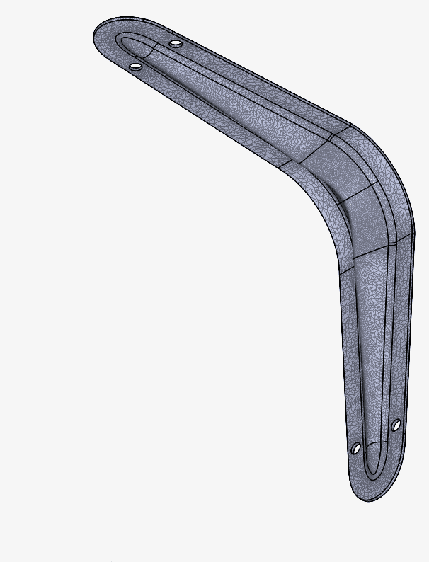
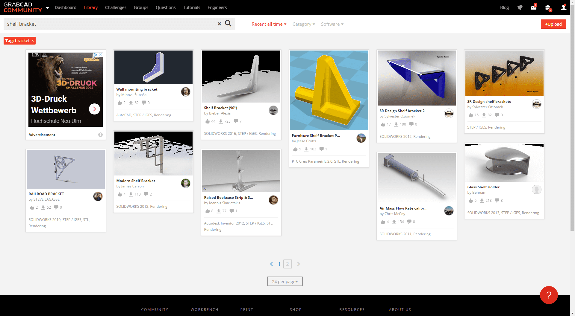
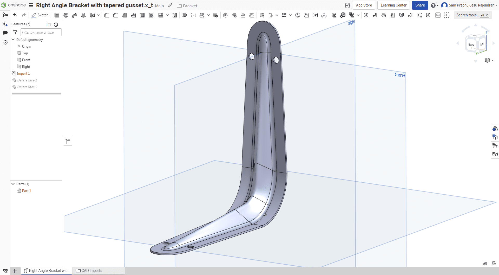
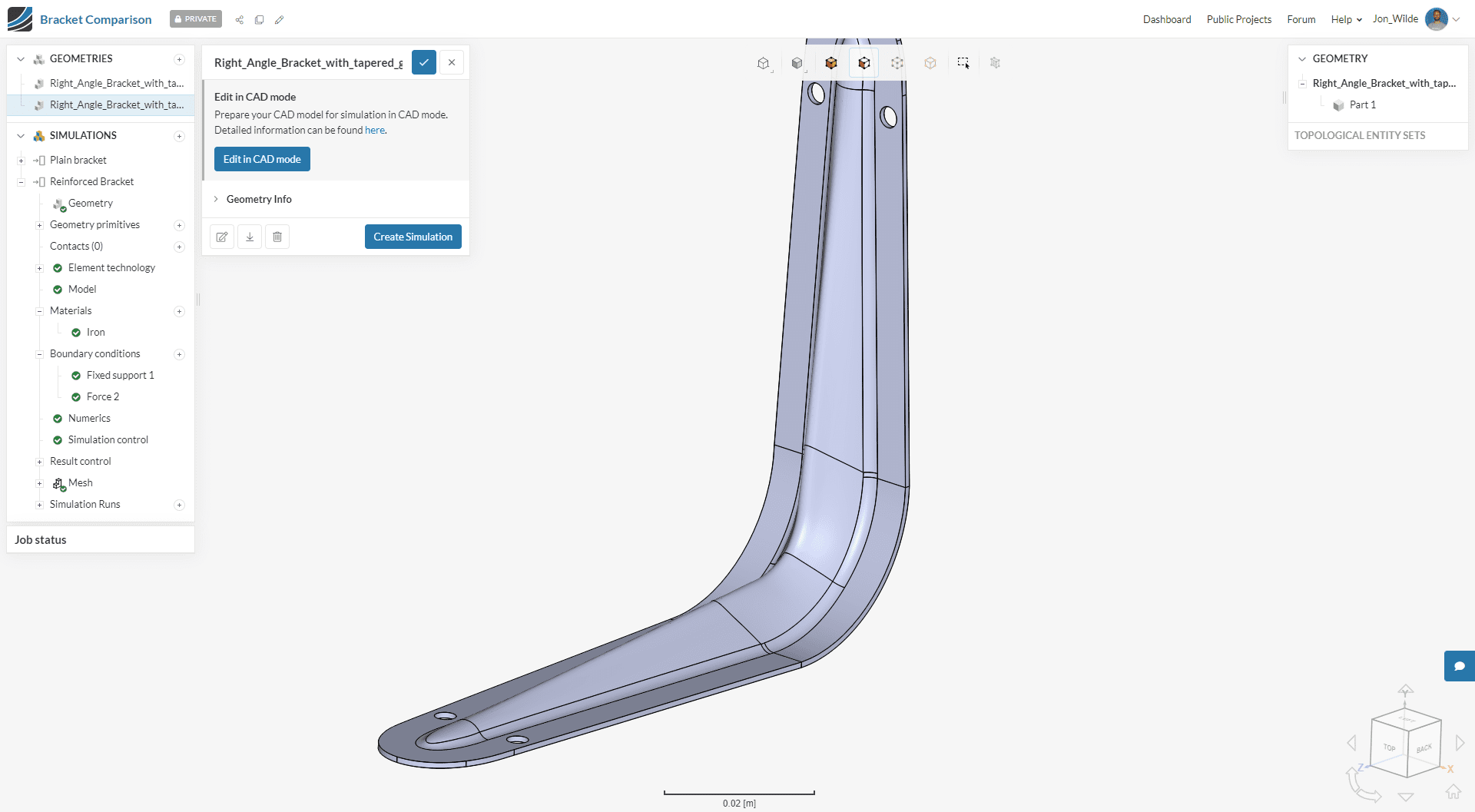
In this project, we have selected a 3D CAD model of a wall support bracket from the extensive library in GrabCAD. Engineers can access different file formats for the same products depending on their preferences. We then open the support bracket model in Onshape, which integrates with SimScale to import CAD assemblies directly. Any CAD preparation, if needed, can be undertaken in Onshape or SimScale. The model is then imported into SimScale, ready for static structural analysis. We have selected the support bracket to investigate its loading response to a 100 Nm load and evaluate its reinforcement’s performance. To do this, we have created a duplicate of the CAD model and removed the reinforcement. We now have a 3D model of a support bracket with and without reinforcement for a comparative study. Removing the reinforcement can be done in Onshape, before importing into SimScale or, using CAD mode, this minor modification can be completed in SimScale directly.
Analysis-Driven Design Insights
Once the CAD models are ready, a few steps are needed to set up a simulation. In the first instance, we have not modeled friction, gravity, separation contacts, or the bolt connections:
- We first define the materials for the support bracket. The default metal steel has been selected. Later we can perform a comparative analysis by duplicating this material and customizing its properties with a higher Young’s modulus, for example. Customized and newly added materials appear in the materials library and can be shared across projects and team members.
- Then we assign structural constraints using a fixed wall boundary condition and a 100 Nm load to the model. In this case, we will output the von Mises (yield) stresses, which is a value used to determine if a given material will yield or fracture. It is used chiefly for ductile materials, such as metals. The von Mises yield criterion states that if the von Mises stress of a material under load is equal to or greater than the yield limit of the same material under simple tension, then the material will give way.
- Finally, we hit simulate, which is also when the meshing takes place, with default settings. Later we will refine the mesh.
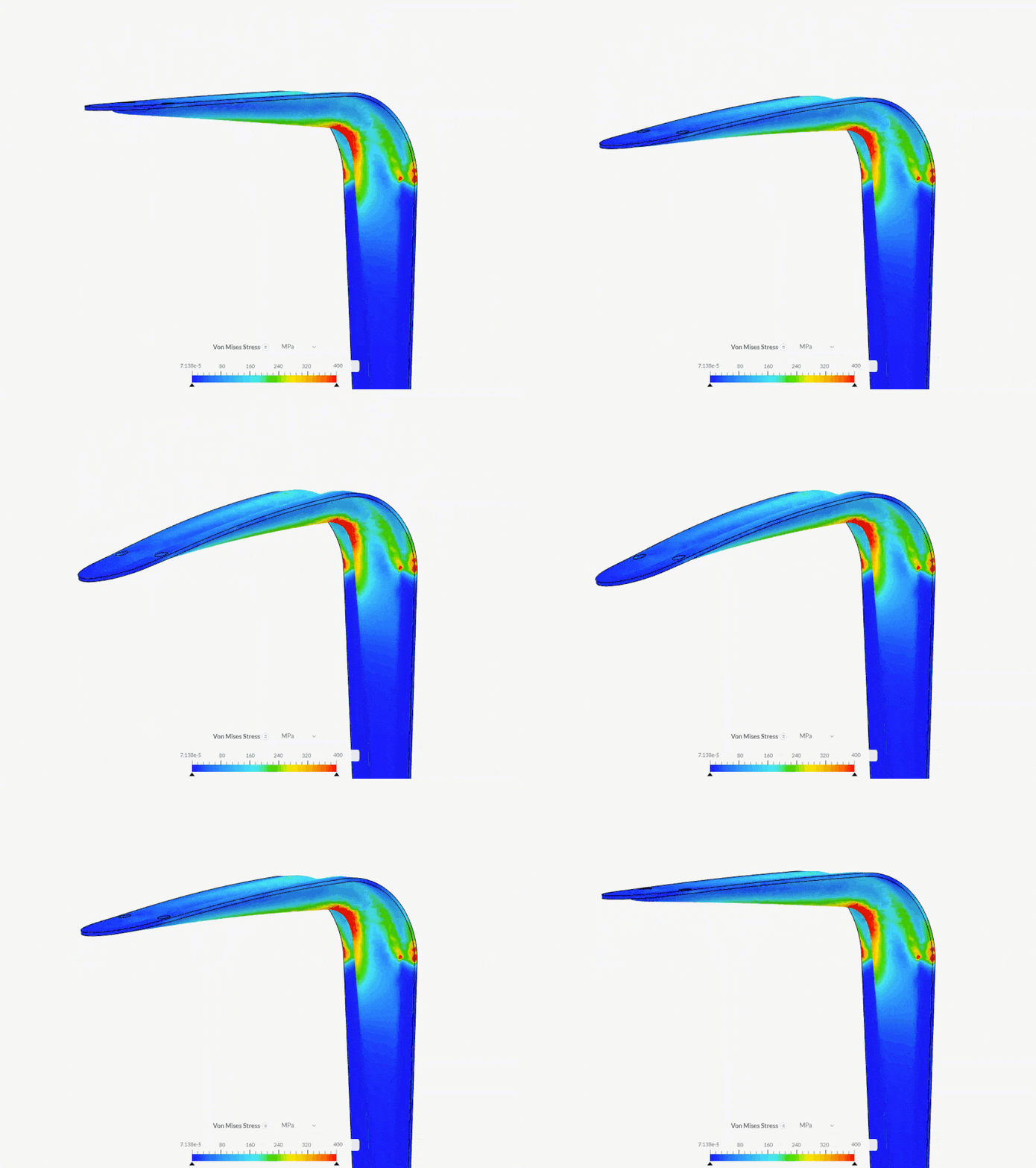
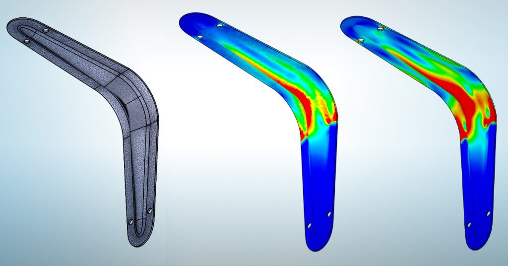
A simple analysis of the two CAD models (with and without the reinforcement) shows us the value of adding the reinforcement. The images below show the load applied displacement from the brackets’ designed state. The image on the right is the CAD model without reinforcement and has an enormously higher displacement of 70 mm compared to the original model (with reinforcement) displacement of only 2 mm. The structural stresses are also much higher and over a larger surface area in the modified model. We might add bolt connections with pre-load stresses with more time and model the wall for more accurate results.
Mesh Refinement
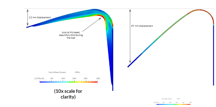
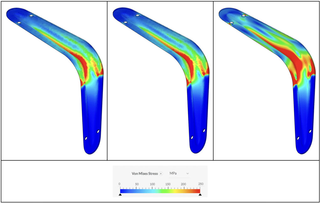
The automatically applied default mesh with a level 5 refinement in SimScale gave us a mesh size of 443,000 cells. The default setting is good enough to refine small features and edges without further guidance. Although the results using the default mesh should not be considered mesh independent, they are accurate and sufficient for early-stage analysis and quick insights. The following mesh we have generated is globally refined at level 8 refinement and might be considered a mid-level quality mesh with 678,000 cells. Finally, we apply a more advanced locally refined mesh where we manually select the surfaces and regions of interest, in this case, the gusset/reinforcement. Here we have applied a maximum edge length of 0.0005 m for the mesh giving us a mesh size of 845,000 cells. The images below illustrate the comparative results between the three meshes.
CAD Cleanup and Meshing for Simulation
Engineers need tools where they can quickly clean up and prepare their CAD models and assemblies to make them simulation ready. Using the inbuilt features in SimScale and the CAD integrations such as Onshape, users can spend less time on tedious CAD operations and more time simulating their designs and extracting valuable performance data. Engineers are further empowered by the parametric simulation capabilities in SimScale and the practically unlimited computing power in the cloud.
Follow along in a step-by-step demo that introduces our 3D CAD and meshing tools for simulation:
