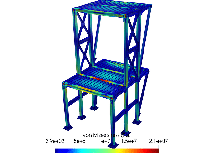
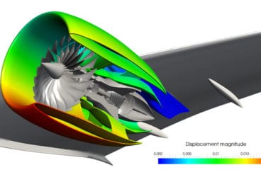
FEA is the acronym for ‘finite elements analysis.’ Based on the finite element method (FEM), it is a technique that makes use of computers to predict the behavior of varied types of physical systems, such as the deformation of solids, heat conduction, and fluid flow. FEA software, or FEM software, is a very popular tool used by engineers and physicists because it allows the application of physical laws to real-life scenarios with precision, versatility, and practicality.
In this article, we discuss the basic questions you have about FEA as a beginner and provide you with links to all the necessary references you need to understand and start using FEA today.
- How Does FEA Work?
- What are Some Use Cases of FEA?
- What are Stress and Strain?
- What Key Industries Use FEA?
- Why is FEA Important?
- How Can I Learn FEA? (With SimScale)
How Does FEA Work?
FEA is the application of the finite element method (FEM) to practical problems. The finite element method is a mathematical procedure used to calculate approximate solutions to differential equations, allowing for its application to real engineering problems. The goal of this procedure is to transform the differential equations into a set of linear equations, which can then be solved by the computer in a routine manner.
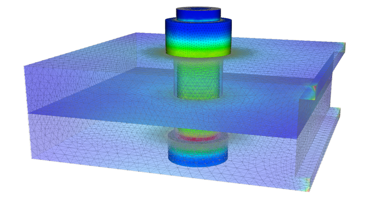
Differential equations are very important and present in many engineering problems because they represent the language in which physical laws are expressed. They connect changes in the internal variables of an object, such as displacement, temperature, or pressure, and their relation with the object’s geometry, physical properties, and external influences acting on it.
The detailed explanation of how this transformation from a physical law into a set of linear equations is performed is beyond the scope of this article, but here is a general overview of the process:
- The physical problem is well defined, with set physical laws to be applied, in the form of differential equations.
- The geometry of the object to be analyzed is defined, with the space occupied by it called the ‘domain’ and the surface enclosing it called the ‘boundary.’
- External influences acting on the boundary or domain are also well defined, such as forces, pressures, temperatures, or heat sources. These are known as ‘boundary conditions.’
- The ‘initial conditions‘ of the object are also well-defined. These are the set of values of all internal variables at the first moment of the problem, for example, initial velocities, pre-stresses, or the initial temperature distribution.
- The domain is then split into small basic shapes known as ‘elements.’ The set of all elements is known as the ‘mesh‘. Also, the points where neighbor elements meet are called ‘nodes.’ The size of the elements will determine the precision of the approximate solution, the smaller being the better. However, a higher number of elements used will increase the demand for computational resources such as memory and processor time.
- Then, all equations and boundary conditions are ‘projected‘ into the nodes, resulting in a finite—but often large—number of linear equations.
- The linear equations are solved by the computer, and the list of resulting variables for each node and element is written into files.
- The resulting data is used to make numerical analysis, visualizations and design decisions.
For more information on how FEA works, check out our guide to FEA by clicking the button below.
What are Some Use Cases of FEA?
Although the finite element method is not bound to a particular type of physical problem, its main field of application is the structural analysis of solids. Structural analysis might include different types of loading and scenarios, but its main purpose is one: to predict whether a given part or structure will safely withstand forces acting on it.
This is achieved—according to the theory of the resistance of materials—by looking at the state of the part in terms of stress and strain. The maximum values obtained by any method (for example, FEM) are compared to allowable values to see if they conform to the safety range. These allowable values are most of the time specified by a design code such as ASCE, ASME, Eurocode, etc.
Some typical use cases of FEA software include:
- Steel or reinforced concrete structures, for buildings and other civil applications, load lifting, etc.
- Industrial equipment, such as pressure vessels, piping, boilers, rotating equipment, etc.
- Manufacturing equipment, such as mills, molds, tooling, etc.
- Automotive, aircraft, or other transport structures, particularly for virtual crash tests.
For more information on use cases of FEA, click the button below to read about FEA in SimScale and some example cases.
What are Stress and Strain?
Two very important concepts to grasp in order to start using FEA for structural assessment are stress and strain, as they are both related to the deformation of solid bodies. These topics are typically covered in depth when learning about the strength of materials, but here we will give a brief introduction.
When a solid body is subject to the action of external forces, such as pressure, contact, or gravity, the body will undergo some deformation. The shape and magnitude of such a deformation depend on many factors, such as the direction and magnitude of the external actions, the geometry of the body, and the rigidity of the constitutive material.
The simplest example of this is the deformation of a spring: when the spring is hung in a vertical position, it is in equilibrium with some characteristic length. If weight is attached to the lower end, the spring will extend, up until reaching another equilibrium point, this time with a longer length.
If the magnitude of the weight is varied, we will notice that the elongation of the spring is proportional to the weight, also known as Hooke’s law, and the constant of proportionality is known as the spring’s ‘rigidity.’
What is Stress?
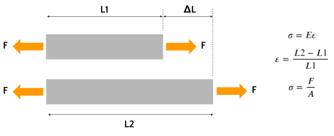
What happens internally, is that the external forces are balanced by forces developed inside the material, which tends to oppose the elongation effect, causing the equilibrium state. These internal forces are known as the material’s ‘stress‘ and are the result of cohesive forces at molecular levels. The higher the activity of the external force, the higher the stress developed by the material will be. Failure theories are based on limit stresses, that is, failure of the element is expected to occur when stress levels surpass a given threshold.
What is Strain?
When trying to write Hooke’s law in terms of material stress, one notices that the elongation of elements is not a consistent measure. If the geometry of a test specimen (e.g., for a uniaxial test) is changed, then the rigidity constant does not generalize for a given material. A special measure of deformation should be considered. This is known as the material ‘strain‘ and has a few different definitions, such as ‘engineering strain‘ or ‘true strain.’ These definitions allow us to state a relation between the material’s stress and strain, using a measurement of the material rigidity known as Young’s modulus.
Although stress and deformation are the main calculations in FEA, they are not the only important predictions that can be made with it. Other very useful information for a given structural system that can be obtained with FEA include:
- Natural vibration frequencies and modes
- Forced vibration (harmonic) response
- Buckling limits and modes for thin structures
- Fracture propagation modes and fatigue life
For more information on stress and strain in FEA, click the buttons below to read about different aspects of stress and strain.
What Key Industries Use FEA?
Automotive
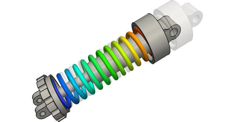
In the automotive industry, FEA software simulations are performed to assess the structural safety of designed components, such as chassis, anchors, suspension, bodyworks, etc. One of the most interesting applications is virtual crash tests, where a dynamical simulation is performed to predict deformations and energy absorption against crash impact. Here is a SimScale project simulating a car suspension’s deformation and stress.
For more information on the automotive industry, click the link below.
Industrial Equipment
For industrial equipment design and engineering, finite element analysis (FEA) software is widely used. In the processing industry, for example, pressure and heat loads are applied to predict stress levels in piping, pressure vessels, tanks, and similar equipment. Another possible use for the industry is the simulation of forging processes for mills, benders, and stampers, to measure stress levels and spring-back magnitude of forged parts.
For more information on machinery and industrial equipment, click the link below.
Civil Engineering and Structural Design
For civil engineering and structural design, FEA software has unleashed the power of fast and accurate analysis, with the possibility of automatically applying code load combos and checking compliance. Typical analysis scenarios include static loading, equivalent static loading, dynamic performance in seismic scenarios, natural vibration modes, and frequencies calculation. Here is an example project performing structural analysis on a steel structure:
For more information on the architecture, engineering, and construction (AEC) industry, click the link below.
Why is FEA Important?
FEA is the defacto technology for detailed stress analysis and deformation prediction across almost every engineering field. As more analysis tools become accessible to designers and engineers, it has a lot of space to grow its presence. As we have been able to see, it is very versatile and powerful, making it a must-have tool in any product design portfolio.
The most recent trend in FEA software is cloud-native simulation services and tools. Companies such as SimScale provide simulation tools that run in the web browser and make use of remote servers for the computing tasks, freeing local resources, and lowering the requirement for powerful hardware and special software installations.
Explore FEA in SimScale
How Can I Learn FEA? (With SimScale)
If you are interested in FEA software and want to start leveraging its benefits in your projects, you can make use of the following resources:
- Sign up for a free SimScale account by clicking on Start Simulating below, where you can set up your simulations in just a few minutes and get real-time support from our experts and engineers.
- Read the SimScale FEA Documentation.
- Read more about FEA on the web: FEA for All, Stress eBook, or SimScale.
You can also check our comprehensive guide on learning FEA by clicking the button below.


